MN zone 2 and NO zone 2 relay elements. Deal of de facto standardization of distance element design took place.
2
Numerical techniques are the newest way to implement distance and directional relay elements.
. A time delayed tripping zone for back-up protection. These designs used analog circuits with semiconductors. 2579-0625 Online 2579-0617 Paper Design of Fuzzy Logic Based Relay for Distance Protection 1 Adedayo Kayode Babarinde 2Philip Adesola Adewuyi and 3Adefemi Adekunle Department of Electrical Electronics.
All distance relays compare voltages and currents to create impedance-plane and directional characteristics. SOPSPOL 90 2 For decades various relay technologies ha ve derived and compared the operating and polarizing signals differently. The number of relay elements required for complete schemes is usually quite large.
One approach to making a distance relay with a computer is to calculate the apparent. It means a mho relay is a voltage restrained directional relay. Free of the inherent inertia of electromechanical devices these distance relays operated very fast.
The mechanism of this device was similar to a digital amplifier reiterating the signal and so permitting the signal which has to be propagated to the desired distance. Free of the inherent inertia of electromechanical devices these distance. Mho Type Distance Relay.
Protective relay applications relay designers introduced distance relay designs based on filtering and coincidence timing by using analogue circuits with semiconductors. There is one type of relay which functions depending upon the distance of fault in the line. Long reaching forward set ground distance elements can pick up for a close-in reverse ground fault on.
For example a four-zone phase and ground mho distance relay requires 24 comparators. The distance relay is a distance protection element designed to measure the faulty point. OLTAGES AND The paper analyzes key parts of todays distance elements.
Quadrilateral distance relay is. Supervise Distance Elements Directional elements add security to all distance elements. These relays are known as distance relay or impedance relay.
Quadrilateral characteristics require even more. The relays then use these digitally filtered values as phasors in such elements as distance overcurrent and overundervoltage. Figure 5 shows very schematically the contact circuits of the principal units.
An electromechanical distance may use a replica scheme. It is also sometimes called an angle impedance relay. Coordination is then obtained by adjusting the time delay of one or both of the overreaching zone 2 elements.
It is not affected by the arc resistance and least affected by the power swing. Reliable enough for protective relay applications relay designers introduced distance relay designs based on filtering and coincidence timing. For transmission-line protection a single-phase distance relay of the impedance type consists of a single-phase directional unit three high-speed impedance-relay units and a timing unit together with the usual targets seal-in unit and other auxiliaries.
More specifically the relay operates depending upon the impedance between the point of fault and the point where relay is installed. A distance element operates when. The operation of this relay depends on the value of the impedance.
Distance element regardless operation of a particular relay design. Zones 1 and 2 preserve continuity of service or. First in order to properly measure the distance to the fault using fundamental frequency voltages and currents all distance elements must go back to the same basic -phase three circuit diagram to tie the measured voltage and current with the distance.
Distance elements are used in line protection schemes for their definite reach. A definite reach is highly desired in distance elements. Many papers and publications provide details on.
Simple overcurrent protection lacks this property and its reach is highly dependent on the source impedance. Download Full PDF Package. October 25 2020.
The remaining two elements will be reactance measuring elements as shown in Fig. FUOYE Journal of Engineering and Technology Volume 2 Issue 2 September 2017 ISSN. Decades of distance element design enhancements the industry arrived at a version of ts that is more distance elemen dependable and secure than in the early days of distance protection but only if the fault current sources behave like synchronous generators.
A distance relay on the Wehrendorf end of the Wehrendorf-Landesbergen 380kV. But the relay which was currently in use today was designed by Samuel Morse in the year 1840. Most static-analog implementations use coincidence-timing techniques.
Distance element considers two signals S1 operating and S2 polarizing that should coincide for at least 180 degrees 90 degrees or 0180 degrees 13. In this relay operating torque is obtained by the volt-ampere element and the restraining torque is developed due to the voltage element. Reverse Ground Faults and Ground Distance Elements The operating quantities for ground distance elements include residual current 3I0.
Mho relay is a high speed relay and is also known as admittance relay. Electromechanical relays do so by developing torques. In the project the starting element will be the quadrilateral distance measuring element.
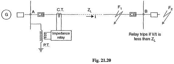
It trips the circuit breaker and closes the contacts when the impedance of the faulty point is less than the impedance of the relay.
Stepped Distance Protection Characteristics For The Relay R1 Download Scientific Diagram
2

Distance Relay Or Impedance Relay Working Principle Types Electrical4u
2

Eight Most Important Distance Relay Characteristics Based On Impedance Comparison Eep

Eight Most Important Distance Relay Characteristics Based On Impedance Comparison Eep
2
Distance Relays Or Impedance Relays Types Definite Distance Relay
0 comments
Post a Comment